Design a Ripple Counter Using Flip-flops for This Sequence
The asynchronous or ripple counter consists of series of flip-flops which are not synchronized by the same clock pulse. Design of asynchronous counter involves several steps from selecting the number of flip-flops to drawing the logic circuit diagram.
Before entering the design of the asynchronous counter, you can go through the construction, operation and timing diagram of the asynchronous counter.
Design steps of asynchronous counter
- Find the number of flip flops using 2n ≥ N, where N is the number of states and n is the number of flip flops.
- Choose the type of flip flop.
- Draw the truth table for asynchronous counter.
- Use K-map to derive the flip flop reset input functions.
- Draw the logic circuit diagram.
Design Problem #1
Design a BCD ripple counter using JK flip flops.
Step 1: Find the number of flip-flops
BCD is the 4-bit number and there are 9 valid states in a 4-bit BCD. Hence 4 flip-flops should be used in the design.
The valid states are 0000, 0001, 0010, … 1001.
Step 2: Choose the type of flip-flop.
Let us design the BCD ripple / asynchronous counter with JK flip-flops.
Step 3: Draw the truth table for BCD ripple counter.
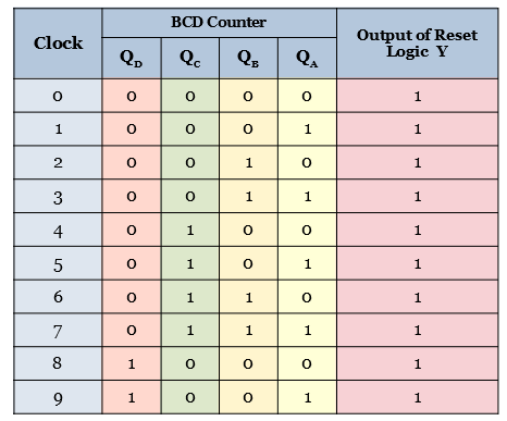
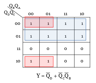
Step 4: Use Kmap to find the reset logic function.
The above truth table for BCD counter is implemented in a Karnaugh map to get the reset logic function.
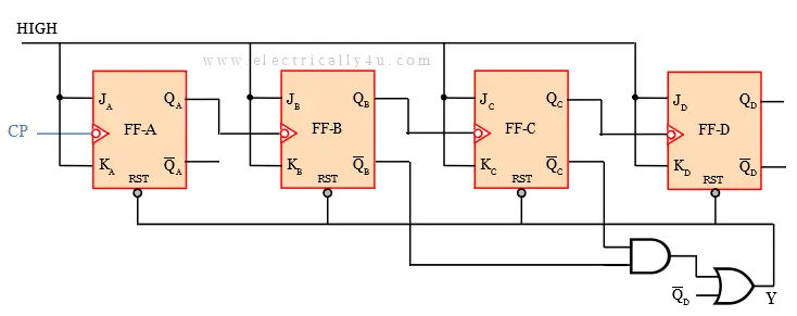
Step 5: Draw the logic circuit diagram.
The logic circuit diagram for BCD asynchronous/ripple counter is drawn as below. It is drawn with 4 flip-flops. Since it is an asynchronous counter, the clock pulse is given only to the first flip-flop. For the other flip-flops, the output of the previous flip-flop is given as the clock pulse for the next flip-flop.
The expression obtained from the K-map is drawn using combinational circuits. The output Y is given as RESET for all the flip-flops.
Design Problem #2
Design a Mod-6 asynchronous counter using JK flip flops.
Step 1: Find the number of flip-flops
Mod-6 counter represents that the counter will have 6 states. Thus, N =6.
The number of flip-flops used for counter design is determined using the formula, 2n ≥ N.
By trial and error method, the value of n is found to be 3. That is the number of flip-flops, n = 3.
Hence the 6 counter states are 000, 001, 010, 011, 100, 101.
Step 2: Choose the type of flip-flop.
Let us design the mod-6 asynchronous counter with JK flip-flops.
Step 3: Draw the truth table for mod-6 asynchronous counter.
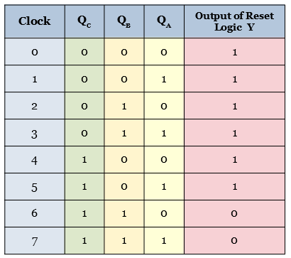
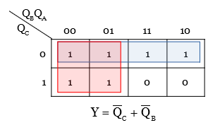
Step 4: Use Kmap to find the reset logic function.
The above truth table for Mod-6 counter is implemented in a Karnaugh map to get the reset logic function.
Step 5: Draw the logic circuit diagram.
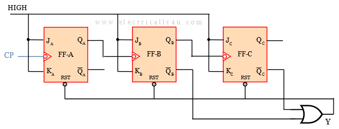
The logic circuit diagram for mod-6 asynchronous/ripple counter is drawn as below. It is drawn with 3 flip-flops. Since it is an asynchronous counter, the clock pulse is given only to the first flip-flop. For the other flip-flops, the output of the previous flip-flop is given as the clock pulse for the next flip-flop.
The expression obtained from the K-map is drawn using combinational circuits. The output Y is given as RESET for all the flip-flops.
An Assistant Professor in the Department of Electrical and Electronics Engineering, Photoshop designer, a blogger and Founder of Electrically4u.
Design a Ripple Counter Using Flip-flops for This Sequence
Source: https://www.electrically4u.com/design-of-asynchronous-ripple-counter/
0 Response to "Design a Ripple Counter Using Flip-flops for This Sequence"
Post a Comment